Modern Physics >
Atomic Physics
|
DCS# ?
|
ATOMIC FORCE
MICROSCOPE MODEL
-
APPARATUS
atomic force microscope
model with sample
|
202-12-B-2 |
laser pointer
|
202-21-B6 |
laptop and LabPro interface
or oscilloscope
|
206
|
cylindrical lens
|
101-06-G3
|
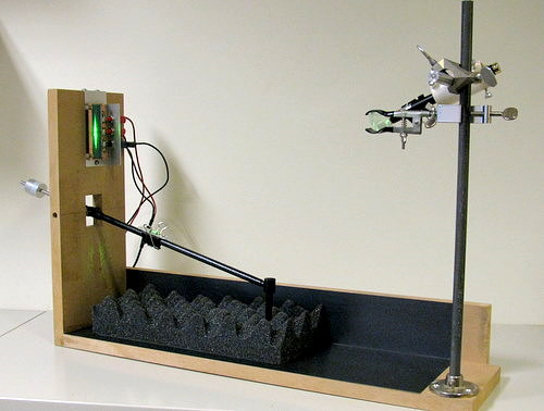
DESCRIPTION
- An expanded laser beam reflects
off of a mirror on the cantilever arm to a pair of solar
cells. An oscilloscope displays the difference between
the two cell voltages, which is related to the position of the
light beam and thus the deflection of the cantilever. As
the sample (a block of acoustic foam) is scanned past the tip
of the probe, the arm deflects and the resulting signal is
displayed. The mirror can be repositioned and the laser
aimed to reflect the light onto a screen to be viewed
directly.
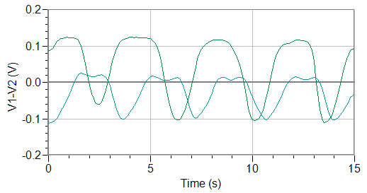
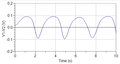
The first graph below shows a scan of the acoustic foam
(green) and an inverted egg carton (blue). The second
shows a scan of the fcc/hcp
model:
NOTES
Use a
cylindrical lens to expand the laser beam vertically. Aim the laser so that the entire
beam strikes the solar cells throughout the travel of the
arm. Connect the two solar cells to two channels of the
oscilloscope or LabPro interface. Display the voltage of
the lower cell minus that of the upper cell (since an upward
deflection of the arm causes a downward deflection of the
reflected beam).
The acoustic foam is asymmetric and the tip of the probe moves
over it more smoothly in one orientation than the other.
Note that to plot Vbottom cell - Vtop cell,
with probes connected so that V1 = Vbottom
and V2 = Vtotal, one should plot 2V1
- V2.
Use the experiment file afmmodel.cmbl.
REFERENCE